Technical and quality requirements:
Waste water and waste gas treatment device design, vacuum pump discharge oil and water, caprolactam polymerization reaction by high thermal decomposition, thermal decomposition discharge toxic smoke, combustion decomposition products are: toluene, xylene, non methane total hydrocarbon, carbon monoxide, nitrogen oxides and other waste gas.
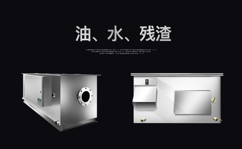
Vacuum furnace wastewater treatment equipment
Unpowered sewage is a new sewage treatment product with unpowered, high efficiency, easy maintenance and convenient operation. It is a new product which combines mechanical method, flow rate method, gap filtration method and biochemical method. It has strong processing capacity and high separation efficiency.
A. Main Structure
The unpowered sewage treatment plant is mainly divided into four functional areas: slag removal area, oil slick separation area, biological disc treatment and drainage part, as shown in the figure:
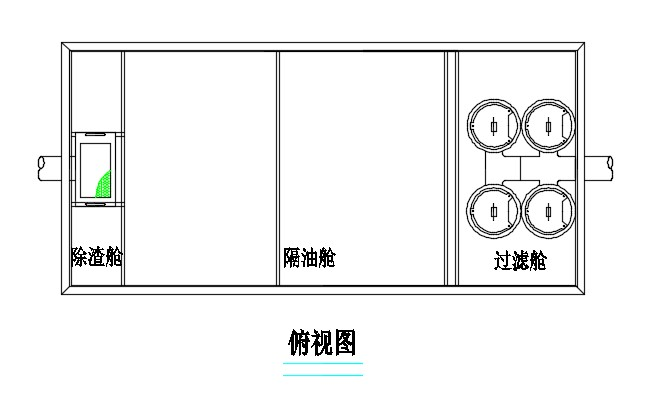
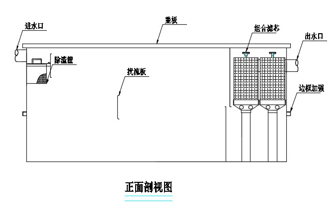
A.
B. Working Principle
Oily sewage enters the first functional zone. The sewage containing oil and scum flows into the slag removal basket through the water inlet pipe, and most of the slag is intercepted and deposited by the slag basket.
The sewage after slag removal enters the second functional area through the partition board. At this time, the floating grease will rise to the water surface quickly. The flow rate of sewage gradually tends to be stable under the action of gravity. The density of oil and water is poor. The floating oil in the sewage will be separated to the sewage surface quickly, so that the impurities and floating grease can be removed and separated. When a certain amount of oil is reached, professional oil collector shall clean and collect oil regularly.
The oil slick removal wastewater enters into the third functional area: disc filter element treatment to remove the small package grease and particles. Its working principle: the wastewater is deeply filtered from the bottom to the top from the lower inlet of the treatment disc. In this process, the sewage flows from the inlet chamber of each layer of treatment discs to the cofferdam drainage area through the dyke. At this time, it is blocked and filtered by the small gaps between discs, so that the small dregs wrapped by oil can be intercepted and filtered. Then, the sewage is collected from the two disk overflow outlets to the outlet channel, and flows out through the outlet of the equipment.
In this way, the large sediment particles are removed, and the fine particles containing oil are isolated. Meanwhile, the suspended oil, soluble oil and suspended particles in the effluent are greatly removed. Finally, the functional requirements of oil-water separation and the pretreatment requirements of oil pollution before discharging into the pipe network are realized.
C. Product Advantages
- Combined with a variety of processing methods, the design is novel, simple and reliable.
- The circular disc filter element is adopted for filtration treatment, with advanced technology and high oil removal effect.
- No power, no energy consumption, very low use and operation cost.
- The integrated structure is adopted, with small floor area and simple and convenient installation and construction.
- The floating oil and sediment are relatively concentrated, which is convenient for discharge, cleaning and collection.
- After treatment, the oil content of effluent meets the requirements of grade III national discharge standard (GB8978-1996) and urban pipe network.
D. Equipment Installation
- During installation, please ensure that the installation foundation surface is smooth and flat, and the foundation area is not less than the bottom plate of the equipment box.
- After the equipment of buried installation is placed, it shall be filled with water and then backfilled. Fine yellow sand or soft soil shall be used around the equipment to prevent the equipment from being damaged by large bricks and gravel. A cofferdam shall be made at the upper opening of the equipment to prevent rain, cement and sand from entering.
- After the equipment installed in the pit is placed, the box is filled with water and cement mortar is used to fill the gaps around to prevent the equipment from floating.
- During the installation, the connecting pipe is installed according to the actual elevation of the sewage pipe network on site, the original sewage pipe at the water inlet of the equipment is flat, and the water outlet of the equipment is connected with the sewage well;
- After installation, first inject clean water into the equipment (the injection height should be equal to the bottom of the drainage pipe), and then introduce sewage.
- Ensure the smooth flow of the drainage pipe network, so that the normal operation of equipment, drainage unobstructed.
- The equipment can also be installed in indoor and outdoor underground and ground, which is suitable for projects with enough installation space, new construction, reconstruction and expansion
- When dealing with large amount of oily wastewater, two or more devices can be installed in parallel to meet the needs of users.
E. Attention
- In order to ensure the normal drainage of the equipment and achieve the normal use effect, the user should timely clean up the generated dregs and oil slick, and do a good job in the daily operation and maintenance of the equipment.
- The equipment cover plate shall bear 100kg and cannot walk or pile up.
- The equipment shall be provided with independent space and fenced off to prevent children from playing close to it
Waste gas treatment equipment
| Item | Name | Material | |
| 1 | Low temperature plasma catalysis | The introduction is as follows | Stainless steel |
| 2 | Photocatalysis reactor | Carbon Steel | |
| 3 | Honeycomb activated carbon adsorption | Carbon Steel | |
| 4 | Main induced draft fan | Carbon Steel | |
| 5 | Controller | Carbon Steel |
Configuration of waste gas treatment equipment
- Low temperature plasma device + photocatalysis device + activated carbon adsorption device
| Structural Style | Fixed bed |
| Material | Carbon Steel |
| Designed Temperature | 120℃ |
| Designed Pressure | Normal Pressure |
| Connection form with pipeline | Flange |
- Main induced draft fan
| Structural Style | Centrifugal type |
| Power | 1.5kw |
| Voltage | 380V·AC |
| Media name | Air |
| Material of air flow contact parts of fan | Carbon Steel |
| Motor protection grade / insulation grade | IP54/F |
| Explosion proof grade of motor | Non explosion proof |
| Connection form with pipeline | Soft connection |
The waste gas treatment equipment is provided as followed:
| Low temperature plasma + photocatalytic equipment + activated carbon adsorption | ||||||||||
| 1 | Item | Air volume(m3/h) | Dimensions(mm) | Power(kW) | Material | QTY | Remark | |||
| Low temperature plasma + photocatalytic equipment + activated carbon adsorption
|
15000 | 2200×1100×1100 | 10 | Carbon Steel | 1set | |||||
| Equipment casing: carbon steel | ||||||||||
| Air inlet and outlet of equipment:DN100mm | ||||||||||
| It contains 4 groups of low temperature plasma modules | ||||||||||
| The interior contains 40 small UV lamps | ||||||||||
| -C-band UV tube exhaust gas treatment lamp (special quartz lamp) | ||||||||||
| -C-band UV lamp light cutting, forging chain, combustion, cracking exhaust gas molecular chain | ||||||||||
| -The C-band UV lamp can catalyze the oxidation of exhaust gas molecules, so that the exhaust gas can fully react with O3 to produce carbon dioxide and water | ||||||||||
| 27 kinds of synthetic catalysts (photooxygenation system, which completely decomposes organic waste gas) | ||||||||||
| The inlet and outlet are equipped with wire mesh to filter the micro particles in the exhaust gas | ||||||||||
| The flow rate of photo oxygen equipment is 3.5m/s, and the residence time of waste gas in the equipment is about 2S, so as to ensure the full contact between waste gas and ozone and efficiently decompose waste gas molecules | ||||||||||
| Electrically controlled insulation plate (PTFE), corrosion resistance, high temperature resistance, acid and alkali resistance, anti-aging, oxidation resistance, hydrolysis and insulation resistance.) | ||||||||||
| Hardware replacement: the UV lamp in the photocatalysis waste gas treatment equipment should be replaced once every 2-3 years. Replace the headlamp tube every 5 years( Warranty 1 year) | ||||||||||
| Centrifugal fan | ||||||||||
| 2 | Item | Air volume(m3/h) | Power(kW) | Material | QTY | Remark | ||||
| Centrifugal fan | 3500 | 1.5 | Carbon Steel | 2 sets | ||||||
| Fan pressure:734Pa | ||||||||||
| Impeller material: Q235 Carbon steel | ||||||||||
| Type:4-72-12#-1.5KW | ||||||||||
| Transmission mode: belt transmission | ||||||||||
| Soft connection of fan inlet:L=300MM | ||||||||||
Low temperature plasma electrostatic adsorption device
With two-stage high and low pressure purification principle, it can effectively purify the plastic industry, chemical industry, polyester industry and lampblack. Large and heavy soot particles are intercepted on the prefilter. Under the action of continuous self circulation of the fan, soot particles continue to enter the purifier. Under the action of Coulomb force of physics, the oil mist and soot particles are purified and adsorbed on the high and low voltage electrostatic field by using the principle of mutual repulsion of the same charge and mutual attraction of different charges.
Generally, the oil mist produced in the process of mechanical atomization mainly exists in the form of droplets with a wide range of droplet diameter. Studies have shown that soot and large droplets are harmful to human lungs. When inhaled and exhaled, they will not be captured by alveoli. Large droplets of oil cannot enter the lungs through the nose and bronchus. Only in the form of droplets, the oil mist particles with diameter less than 5um can reach the alveoli smoothly and precipitate in the lungs, thus causing great harm to the human body.
UV photo oxidation high efficiency catalytic device
It can effectively remove VOC, inorganic compounds, hydrogen sulfide, ammonia, mercaptan and other major pollutants, as well as all kinds of odor, with the highest deodorization efficiency of more than 99%.
Activated carbon adsorption device
Activated carbon adsorption can adsorb and recover the waste gas of benzene, alcohol, ketone, benzene, ester, gasoline and other organic solvents, which is more suitable for the treatment of waste gas with small air volume and high concentration. Therefore, spraying, food processing, printed circuit board, semiconductor manufacturing, chemical industry, electronics, leather industry, latex products industry, papermaking and other industries can choose. Activated carbon adsorption equipment mainly uses porous solid adsorbent. Activated carbon has adsorption function, which can effectively remove organic pollutants, color and taste in industrial waste gas. It is widely used in the end treatment of industrial organic waste gas purification with good purification effect. After the gas enters the absorption tower through the pipeline, there is a diffusion process between two different phase interfaces. After the diffusion, the gas is sucked out by the fan and discharged.
Description of working principle
The organic and inorganic gases or particles are collected, and the gas transported by pipeline enters the photocatalysis. After the first decomposition, when the organic gas enters the activated carbon tower, the wind speed drops instantly, and the larger particles in the gas will naturally settle into the bottom of the tower. Part of the organic gas dissolved in the gas flows into the activated carbon filter layer along the gas flow direction. When the organic gas enters the carbon layer, the organic gas is absorbed into the carbon by the activated carbon. The clean air passes through the carbon layer and enters the outlet chamber, and the gas is discharged into the atmosphere after mechanical self absorption. In the adsorption process of activated carbon, the carbon will have a saturation period. The process of activated carbon saturation is directly related to the concentration of gas and working time. Activated carbon adsorption box is a kind of dry waste gas treatment equipment. It is composed of a box body and an adsorption unit filled in the box body. According to the number of adsorption units and air volume, it can be divided into a variety of specifications. Different fillers can be selected for the activated carbon adsorption box to treat a variety of different exhaust gases.
It mainly includes three categories:
- acid waste gas and acid mist
- alkaline waste gas
- Organic waste gas and odor
Description of adsorption process
During the working process, the waste gas in the warehouse is discharged to the photocatalytic device by the exhaust fan, and then enters the activated carbon adsorption box. At this time, when the organic waste gas passes through the activated carbon, the solvent is adsorbed on the surface of the activated carbon, and the gas is discharged to the outside by the rear induced draft fan (clean gas after treatment).
Activated carbon adsorption tower is a kind of high efficiency, economic and practical purification and treatment device for organic waste gas, and an environmental protection equipment product for waste gas filtration and adsorption of peculiar smell.
Activated carbon adsorption tower has the advantages of high adsorption efficiency, wide application range, convenient maintenance and simultaneous treatment of various mixed waste gases. The equipment is an adsorption equipment for purifying high concentration organic waste gas and spray painting waste gas. It uses the intrinsic strength of activated carbon to adsorb organic waste gas molecules in combination with the function of fan.It can adsorb benzene, alcohol, ketone, ester, gasoline and other organic solvents. We design the adsorption time according to the different gas pollution factors, and then determine the adsorption area according to the amount of waste gas. Each project is a new design.At the same time, according to the characteristics of exhaust gas emitted by different processes, such as exhaust gas temperature, whether there is oil mist, dust and other relevant parameters, the pre-treatment device or functional section such as cooler and filter is built or added in the inlet part of exhaust gas equipment. Good protection of the adsorption section, to ensure that the adsorption tower in the efficient state of operation.
Characteristics of activated carbon
Activated carbon is the most suitable adsorbent for adsorption of organic solvents in waste gas. This is because other adsorbents are hydrophilic and can adsorb water molecules in the gas, while for nonpolar or weak polar organic solvents, the adsorption rate is low. On the contrary, activated carbon is hydrophobic and has high adsorption efficiency for organic solvents. In addition, the specific surface area of activated carbon is much higher than that of other adsorbents, which is about 500 ~ 1500 m2 / g. Therefore, in the purification of organic solvent waste gas, activated carbon is often used as adsorbent. The adsorption capacity is an important parameter reflecting the adsorption capacity of activated carbon. Adsorption capacity refers to the weight of the material adsorbed by the unit weight of activated carbon in the adsorption equilibrium state. The adsorption capacity varies with the chemical characteristics of various substances in the gas, the temperature of the gas and the concentration of the adsorbed substances in the gas. For homologous compounds, the higher the molecular weight is, the higher the boiling point is, and the larger the adsorption capacity is. Except for low boiling point alkaline gas, the adsorption capacity of activated carbon is about 10 ~ 40%, generally about 25%.
The influence of the temperature and concentration of the gas on the adsorption performance of activated carbon is studied. Under the condition of isothermal adsorption, the higher the concentration of harmful substances in the exhaust gas, the higher the adsorption rate of the activated carbon. For different temperature exhaust gas, the lower the temperature of the exhaust gas, the higher the adsorption rate of activated carbon.
Main Parameters as followed
| Main components | Activated carbon |
| Dimensions | 100×100×100mm |
| Thickness | 0.5~0.6mm |
| Bulk density | 0.38~0.42g/ml |
| Specific surface area | >700m2/g |
| Benzene absorption | ≥30% |
| Compressive strength | positive pressure>0.8MPa
negative pressure>0.3MPa |
| Adsorption rate | 23-25%(Dynamic measurement) |
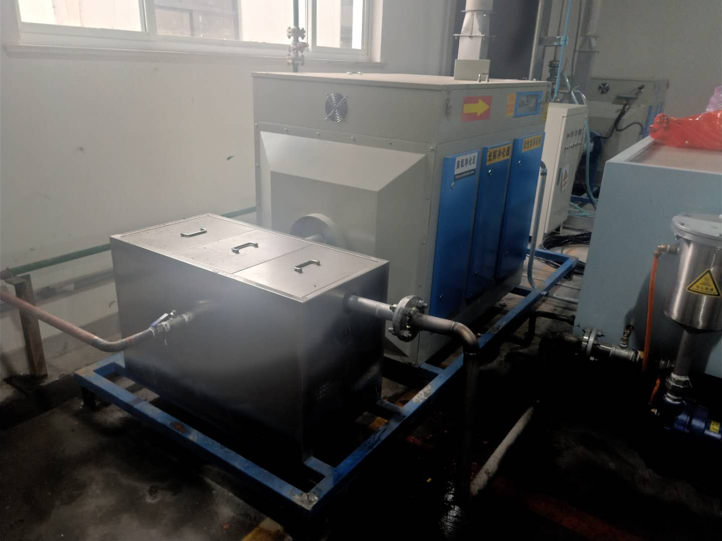
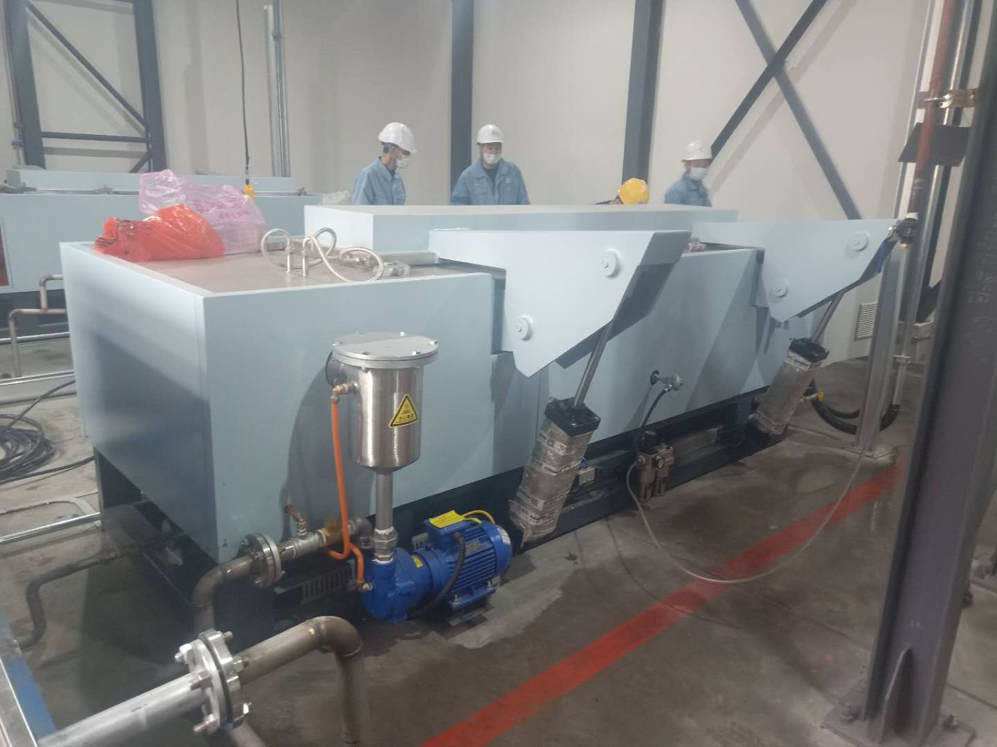
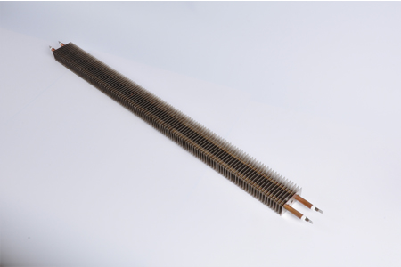
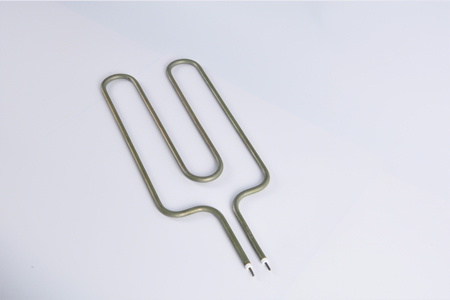
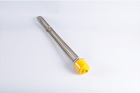
Pictures For Reference
Leave A Comment